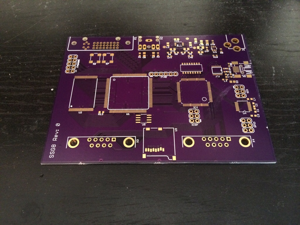
Back on main project. I’ve got firmware that compiles, so it’s time to order the boards. Whlie I’m waiting for them to arive I start tweaking on my video unit. I found a way to double it’s performance, all I have to do is add another clock. This should be fine, I already had that clock hooked up to a PLL. But wait, what’s this, a new and interesting error message I’ve not seen before. My clocks are unroutable, but how. As suggested by the most useful information source ever, some random person on some random forum, I tried compiling without my pin constraints file and it works. So once again I have run into a pin assignment error. What I don’t get is why it didn’t show up until I added this clock but that input clock is plugged into a PLL instance. Surly you know what comes next, to the data sheets! Hmm, the data sheet says clock networks are complicated and you should verify complex designs with the compiler. Well [explitive deleted]. After many hours of carefully studying the data sheet and making random changes to the code I came to the conclusion that the second PLL wasn’t actually being used. Because of the frequencies I was using and the fact that I wasn’t changing the phase of the clock I didn’t strictly need a PLL, just a clock doubler. So instead of using the entire PLL block I instanced the compiler picked a few other misc clock resources. To fix it I’d need to swap a few signals and move the clock input a few pins over so it could be routed to the second PLL because the clock input pins can only be routed to one of the PLLs. While I was working this out, the boards arived.
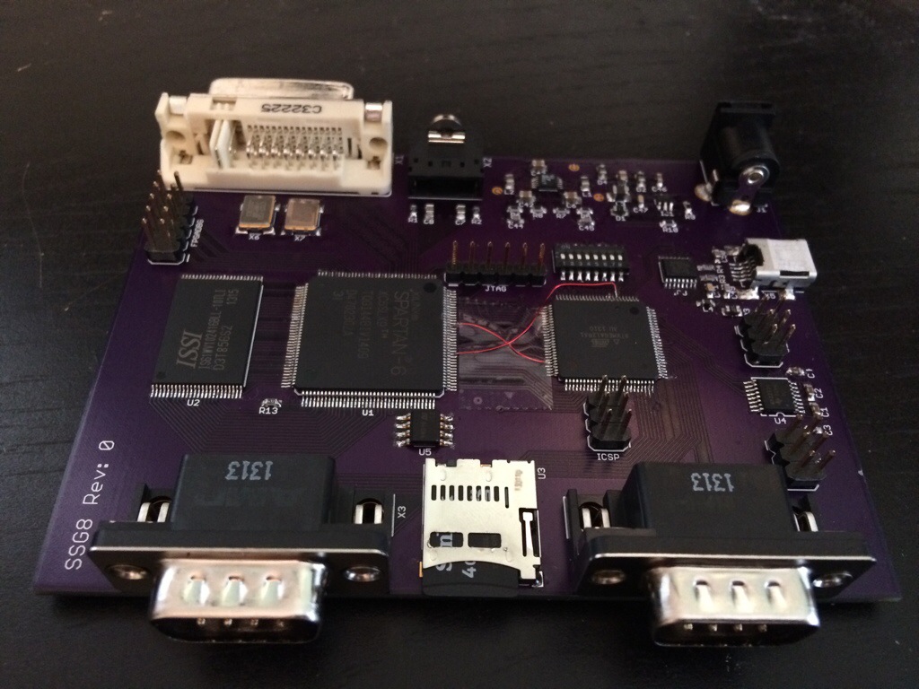
Time for some hardware verifacation. I plugged it in and it didn’t burst into flames, I’m off to a good start. DVI works, it’s actually running at a higher frequency this time. I’m outputting a 720p60 image this time using the built in serializers, pixel doubled from 360p60. I tried it before and after making the board mod. Before the mod I saw some glitches that looked like they were in the logic clock domain. Like it would use the wrong level data periodicly. I suspected the clock I’m using (which is from the microcontroller) may not be stable enough. A PLL can, and did, clear that right up. I haven’t tested the audio DAC yet, but it’s low risk. The FPGA lives, so does it’s config memory. The FPGA can access the SRAM just fine. Though I am running it a little slower than I hoped I would. I suspected this might be the case, I was trying to run it almost at it’s maximum theoretical speed ignoring propagation delays. I don’t have any tricks up my sleve to improve this, but I’ve heard other people have tricks up their sleves that may help. If I can just get them to lend me their coats maybe I can find the tricks up their sleves and use them. The MCU debug port (USB to UART bridge) works, both spare RS323 UARTS work. The MCU can read the config dip switch and access the SD card. The MCU joystick port 1 works fine, joystick port 2 is acting like it’s got a solder bridge, but I haven’t found one. The FPGA debug pins are working (and quite useful).
While ckecking this I ran into another problem. My debugger stopped working entirely, I had to update it’s firmwre to get it to work unreliably. My JTAG programmer works once and then stops. My logic analyzer works on one USB port for a few times and then I have to switch to another port. And even my USB serial adapter is hit and miss. Why… because windows 8. I tried to press the screw it start over button. My favorite thing about windows 8, and it didn’t work. It said I had missing files. Why… because I upgraded from 7 to 8 then 8 to 8.1? It asks me to insert install media, which I don’t have because I upgraded instead of buying a full disk. How do I fix this, do I have to buy another copy of windows just to get the full install disk. I downgraded to windows 7 and now my USB devices are reliable again. As an added bonus the Xilinx tools crash less now too. Wonderful.
Now on to the MCU to FPGA to SRAM interface. This worked fine as an async pass through, but with the SRAM controller and arbiter in the loop it doesn’t. I output the control signals on the FPGA debug pins and probed them, nothing. So I output the clock on the debug pins and hooked it up to the scope, because checking the clocks is now a mandatory part of my diagnostic procedure. Bingo, it’s changed frequency, but why? The debugger is running, it changes when the debugger is running and then switches back when it’s not. That makes sense I guess, the debugger takes over and supplies it’s own clock. But it’s also a problem, and an important little detail I haven’t found in the data sheets. When the clock changes like that the PLL loses lock. So how do I fix this. Two ideas come to mind, mod the board adding another oscilator. Feed that oscilator into both the FPGA and the MCU. I like that solution, but it takes a board rev, or maybe I can solder on the oscilator dead bug style. Another option, feed the locked and reset signals into the MCU and have it reset the PLL when it looses lock. This will work and redefining a few signals or bodging then in is doable, but it has the side effect of resetting some of the logic along with the PLL. It’s a problem, but one I can work around until I can rev the board. I need the MCU and FPGA running off the same clock so the FPGA can register signals on the MCU to FPGA memory interface reliably. With this change the MCU can access the SRAM reliably, next up is getting the MCU to access the video and audio unit config interface. And that brings us up to date.
Lessons learned: FPGA clock networks are complicated. Sometimes you just can’t win.


