About two months ago I was once again sidetracked by another project. I had a very specific problem. I have two software protection keys from the same company for two different sets of software. This company unfortunately didn’t have the foresight to make these two keys compatible. So I had to physically remove one key and insert the other key to get the software to work. This was getting tedius and in a process I’ve otherwise been able to automate. A quick search on my favorite parts site, digikey, shows a few USB hub ICs and I know there are USB microcontrollers around. This is a problem I can solve. Get a hub, connect one port to the USB microcontroller, the other ports can go to the devices, then have the microcontroller recieve commands via USB to power the other two ports on and off. I looked for an existing commercial solution, but what I found went the other way. Selecting one USB devices between mutliple PCs instead of selecting between multiple USB devices connected to one PC. I might could have found an existing device if I looked harder, but life is a journey, rock it. And so I present to you this thing I made.
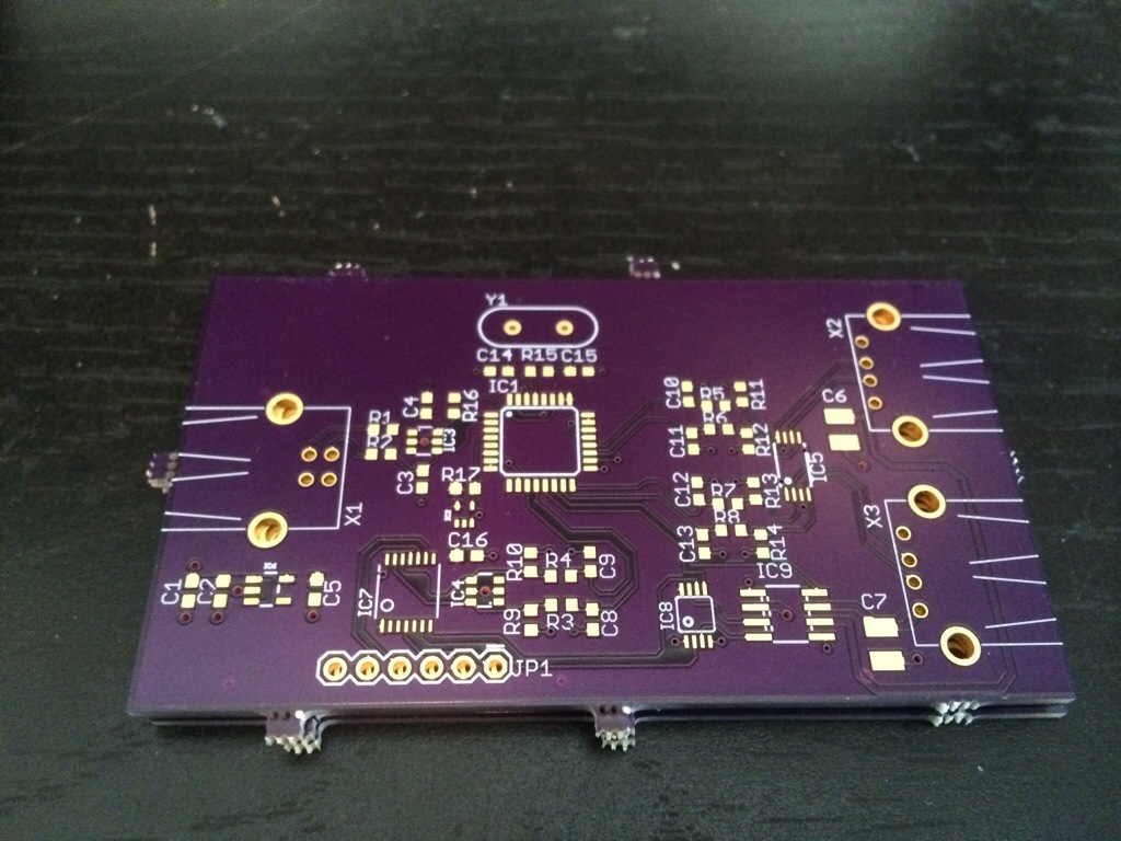
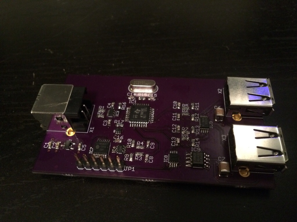
It’s pretty simple, I just followed the reference design for the USB hub and whacked in the smallest, cheapest USB microcontroller I could find, following it’s reference design as well. It’s a PIC16LF1454. Microchip even provides a driver framework which does most of the work for you and samples to get you running quick. Of course something has to go wrong. Murphy knows me well, sometimes I wonder if he is a benevelant being who knows I won’t learn anything if I don’t make mistakes. And Murphy does so want me to learn. The first problem I encountered is the debugger doesn’t work under windows 8, because… windows 8. I solved this by connecting to the debugger under Linux and updating the firmware. The next problem I encountered is that I couldn’t get windows to recognize the microcontroller after loading any of the samples. First I hooked up the microcontroller seperately, directly to the computer to debug just it. Windows sees the device but doesn’t recognize it when I run the debugger. I noticed I could output the clock on one of the pins and on a whim decedied to enable it and probe it on my scope. Oddly enough the output wasn’t the right frequency. Score one for dumb luck. It turns out the samples support using an internal and external oscilator. I had already verified the samples were set for the internal oscilator and the config bits were also set correctly. It turns out I had to add a few lines to change the internal oscilator frequency. Fixed that and now it’s running.
I hooked up the complete board with the new firmware and still no dice. I probed the USB hub and all the device power enable signals are deasserted, why, because all the the overcurrent signals are asserted. The microcontroller overcurrent signal I just plain screwed up. I connected the active low signal to ground, meaning it was asserted. Woops. The next issue was a few missing pullup resistors. The reference design calls out the power switch IC I’m using, but it didn’t include the pullup resistors. I didn’t check this against the power switch data sheet, which looking at now, clearly indicates they are required. Woops again. Luckily my top layer has a power pour so I can just scratch off the solder mask here and there, cut a trace, drop in a solder bridge, whack in a few resistors, and now all is well. I made those changes to the board, but I haven’t gotten new boards manufactured.
Lessons learned: trust your data sheets, but not blindly, verify them against other data sheets if possible. SC70-3 chips are hard to hand solder.